
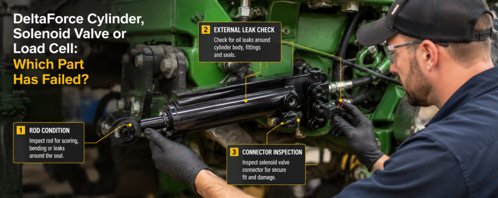
When one planter row shows low downforce, poor ground contact, delayed movement, or an abnormal reading on the 20|20 monitor, the hydraulic cylinder is often blamed first. However, a DeltaForce row combines several components that must work together: the hydraulic cylinder, solenoid-controlled valve, load cell, electrical connections, hydraulic supply, and mechanical row-unit linkage.
Replacing the cylinder without confirming the source of the problem may not correct the fault. The same is true for replacing a load cell when the real problem is hydraulic pressure or mechanical binding.
This guide explains how to separate cylinder, solenoid valve, and load-cell problems before deciding which component requires repair or replacement.
How the Three Components Work Together
The load cell measures the force at the row unit and sends that information to the control system. Based on the measured load and the selected downforce target, the 20|20 commands the DeltaForce system to apply lift or downward force.
The solenoid-controlled valve regulates hydraulic pressure to the DeltaForce hydraulic cylinder. The cylinder then converts that hydraulic pressure into mechanical force at the row unit.
A simplified control sequence is:
Load cell reading → 20|20 command → solenoid valve response → hydraulic cylinder movement → changed row-unit force
Because these components operate as a closed control loop, one failed component can make another component appear defective. For example, a bad load-cell reading may cause the system to command the wrong force even though the valve and cylinder are working correctly.
First Determine Whether the Problem Affects One Row or Multiple Rows
Before focusing on an individual component, compare the affected row with the rest of the planter.
When only one row behaves differently, the fault is more likely to be local. Possible causes include:
- Load cell or load-cell connection
- Solenoid wiring or connector
- Integrated valve
- Hydraulic cylinder
- Local hose or fitting
- Damaged mounting or mechanical linkage
When several rows are affected simultaneously, check common system conditions first. Low hydraulic supply pressure, a manifold problem, system configuration, electrical power, or air in the hydraulic circuit may affect multiple rows.
This first comparison helps prevent the unnecessary removal of a good cylinder.
Review the DeltaForce Diagnostic Data
The 20|20 diagnostic screen provides row-by-row information that can help identify which part of the control loop is not responding as expected.
Depending on the system version and configuration, the diagnostic information may include:
- Load-cell reading
- Solenoid voltage
- Commanded pressure
- Commanded force
- Net applied downforce
- Hydraulic supply pressure
Precision Planting states that the supply-pressure reading should be above 2,250 psi for optimal DeltaForce performance. When supply pressure is inadequate, several rows may respond weakly even though their individual cylinders and solenoids are serviceable.
Do not evaluate one value in isolation. Compare the abnormal row with adjacent rows under the same operating conditions.
Signs That the Load Cell May Be the Problem
A load-cell problem should be suspected when the force reading is unreasonable or inconsistent with the physical condition of the row unit.
Possible indications include:
- One row shows a very different load reading while its physical position appears normal.
- The reading changes suddenly without a corresponding movement of the row unit.
- The system commands unnecessary pressure because it believes that the measured force is too low.
- The affected row behaves differently in automatic mode but appears more normal when the system is evaluated under controlled manual conditions.In automatic mode, the 20|20 continuously adjusts each row according to load-cell feedback. In manual mode, the system applies a specified force without continuously correcting each row according to its individual load-cell reading.If a row behaves abnormally mainly in automatic mode but appears more stable in manual mode, inspect the load cell, calibration, mounting position and mechanical load path more closely. However, this comparison alone does not prove that the load cell has failed.
- The diagnostic screen reports an abnormal load-sensor status.
The load-sensor diagnostic table may show the current reading, sensor status, source, reference value, and calibration information. Precision Planting identifies a healthy reference-value range of 28 to 36 and notes that the system may ignore a load sensor when it detects a suspected sensor issue.
However, an unusual force reading does not always prove that the load cell has failed. A bent bracket, worn pivot, soil packed around the row unit, or mechanical binding can transfer force incorrectly and affect the sensor reading.
Inspect the mechanical structure before ordering a new sensor.
Signs That the Solenoid Valve or Electrical Circuit May Be the Problem
The solenoid controls the valve that directs hydraulic pressure to the DeltaForce cylinder. A problem in the coil, wiring, connector, or valve can prevent the cylinder from responding correctly.
Possible signs include:
- No solenoid voltage is displayed for the affected row.
- The commanded force changes, but the solenoid voltage does not respond.
- The cylinder does not move even though hydraulic supply pressure is available.
- Movement is intermittent and changes when a connector or harness is disturbed.
- The row fails the voltage-current health check.
- The cylinder moves in one direction but does not respond correctly in the other.
When the Electrical Circuit Is More Likely at Fault
Suspect the electrical circuit when the affected row shows no solenoid voltage, fails the Voltage Current Test, or responds intermittently when the wiring harness or connector is moved.
Check the connector, wiring, solenoid coil, power supply and system configuration before removing the hydraulic cylinder.
When the Hydraulic Valve May Be at Fault
Correct solenoid voltage does not confirm that the hydraulic valve is operating correctly. The solenoid coil may be energized while a valve cartridge remains contaminated, restricted, worn or mechanically stuck.
If voltage is present but the cylinder does not respond normally, evaluate the valve, hydraulic flow, cylinder and mechanical linkage together.
The official DeltaForce voltage-current test cycles power to each solenoid and checks for electrical shorts and high current. The row units do not move during this test, and the system provides a pass-or-fail result for each row.
A normal electrical test does not completely eliminate the valve as a possible cause. The solenoid coil may receive the correct voltage while the valve spool or cartridge remains contaminated, restricted, worn, or mechanically stuck.
This is why electrical information must be considered together with hydraulic response.
Signs That the Hydraulic Cylinder May Be the Problem
The cylinder becomes the stronger suspect when the electrical and sensor data appear reasonable, but the row still cannot generate or maintain the required force.
Possible cylinder-related evidence includes:
- Oil appears around the piston-rod sealing area.
- The piston rod is bent, scored, corroded, or damaged.
- The cylinder moves without load but becomes weak under working load.
- The row gradually loses applied force without an external leak.
- Performance worsens after the hydraulic oil warms.
- The cylinder moves unevenly after air has been properly purged.
- The affected row does not hold force while comparable rows remain stable.
Loss of force without visible oil leakage may be caused by internal bypass. However, leakage through the integrated valve can create similar symptoms. A pressure-holding problem should therefore not automatically be blamed on the piston seal.
For a broader inspection process covering external leakage, trapped air, internal bypass and repair feasibility, see our DeltaForce Hydraulic Cylinder Repair and Troubleshooting Guide.
Controlled hydraulic testing may be needed to determine whether pressure is bypassing inside the cylinder or through the valve. This work should be performed by a qualified technician who understands the circuit and can safely manage trapped hydraulic pressure.
Do Not Confuse Trapped Air With Component Failure
Air may enter the circuit after cylinder replacement, hose repair, installation, or any other work that opens a hydraulic line.
Trapped air can cause:
- Delayed response
- Jerky movement
- Uneven cylinder travel
- Inconsistent applied force
- Different movement between rows
Precision Planting recommends running the air-purge test after installation and whenever hydraulic lines have been opened. The test cycles pressure to each cylinder and may need to be performed several times to remove air completely.
Complete the correct air-purge procedure before concluding that a new or recently serviced cylinder is defective.
Use the Applied Force Test to Evaluate the Complete Row
The Applied Force Test evaluates the hydraulic and mechanical response of the DeltaForce system.
During the test, all row units should rise and then lower individually in sequence. The operator must visually determine whether the system passes. An Advanced Applied Force Test is available when further diagnosis is required.
The movement pattern can provide useful clues:
| Test result | More likely area to investigate |
|---|---|
| One row does not move and has no solenoid voltage | Wiring, connector, control configuration or solenoid |
| One row receives voltage but does not move | Valve, hydraulic restriction, cylinder or mechanical binding |
| Row moves but the load reading remains unreasonable | Load cell, sensor mounting or mechanical structure |
| Row moves but cannot maintain force | Cylinder internal bypass, valve leakage or insufficient pressure |
| Multiple rows move weakly | Supply pressure, manifold, hydraulic source or trapped air |
| Movement is jerky after hydraulic work | Air in the circuit or restricted hydraulic flow |
This table is a diagnostic starting point rather than a final component test.
A Practical Diagnostic Sequence
Use the following order to avoid replacing parts unnecessarily:
- Inspect the complete row unit.
Check hoses, fittings, connectors, mounting pins, linkage, visible leakage, and piston-rod condition. - Compare the affected row with adjacent rows.
Determine whether the problem is isolated or system-wide. - Review the 20|20 diagnostic values.
Compare load-cell reading, solenoid voltage, commanded pressure, applied force, and supply pressure. - Run the voltage-current test.
Investigate electrical faults before removing hydraulic components. - Purge air when the hydraulic circuit has been opened.
- Run the Applied Force Test.
Observe whether the row receives a command and produces the expected movement. - Perform controlled component testing.
When the cylinder or valve remains suspect, use suitable hydraulic test equipment and safe pressure-isolation procedures.
This sequence moves from simple external checks to more specialized testing.
When Should the DeltaForce Cylinder Be Replaced?
A cylinder replacement becomes more appropriate when testing points to the hydraulic actuator and inspection reveals:
- A bent or deeply scored piston rod
- Serious corrosion or surface pitting
- Internal bore damage
- Structural or mounting deformation
- Damage to the valve interface
- Repeated leakage after previous repair
- Internal bypass that cannot be corrected reliably
- Lack of correct repair parts or verified repair specifications
Before purchasing a replacement, record the original part number, planter make and model, port arrangement, mounting details, cylinder photographs, diagnostic readings, and required quantity.
AiSoar manufactures replacement Precision Planting hydraulic cylinders for applications associated with the 729602 reference and related cross-reference applications. Before ordering, check the product details and provide the original part number, planter model, cylinder photos and required quantity so that compatibility can be confirmed for the specific row-unit configuration.
Diagnose Before Replacing Parts
A weak or unresponsive DeltaForce row does not automatically mean that the hydraulic cylinder has failed. The load cell may be reporting incorrect force, the solenoid may not be controlling the valve, hydraulic supply pressure may be inadequate, or the mechanical row unit may be binding.
Using the diagnostic screen, health checks, visual inspection, and controlled hydraulic testing makes it possible to narrow the problem before replacing expensive components.
When the evidence points to the cylinder, send AiSoar the original part number, planter model, cylinder photos, diagnostic data, and a description of the row’s behavior. Our engineering team can help evaluate whether the cylinder requires further testing, repair, or replacement.


