
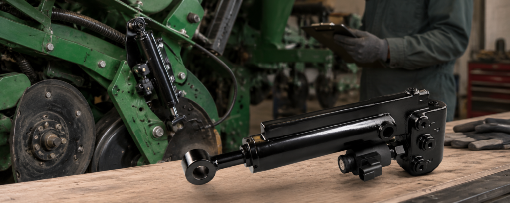
A planter downforce cylinder can lose performance without showing any visible oil leak. One row may gradually lose applied force, respond more slowly than neighboring rows, or fail to maintain consistent ground contact even though the cylinder body, hoses, and fittings remain dry.
These symptoms may indicate internal hydraulic bypass, but they do not automatically prove that the cylinder’s piston seals have failed. In an active hydraulic downforce system, similar behavior can also be caused by an integrated valve, incorrect load-cell feedback, trapped air, insufficient supply pressure, or mechanical binding at the row unit.
Accurate diagnosis should therefore begin with system comparison and diagnostic data before the cylinder is removed.
Quick diagnosis: If one planter row loses downforce without an external oil leak, internal cylinder bypass is possible. However, supply pressure, load-cell feedback, solenoid valve response, trapped air and mechanical binding should be ruled out before the cylinder is removed or replaced.
What Is Internal Leakage in a Downforce Cylinder?
Internal leakage occurs when pressurized oil passes across an internal sealing surface instead of remaining in the intended cylinder chamber.
In a conventional hydraulic cylinder, this commonly means oil bypassing the piston seal from the high-pressure side to the lower-pressure side. The oil remains inside the hydraulic circuit, so there may be no visible external leak.
As internal bypass increases, the cylinder may still move without load but become unable to generate or hold the required force under working conditions.
In a planter downforce system, the situation can be more complicated because the cylinder may work together with an integrated solenoid-controlled valve. Pressure loss through the valve can produce symptoms similar to piston-seal bypass. A loss-of-force complaint should therefore be treated as a hydraulic circuit problem until testing isolates the failed component.
Common Symptoms of Possible Internal Bypass
Possible indications include:
- One row gradually loses downforce while adjacent rows remain stable.
- The cylinder responds to commands but cannot maintain the applied force.
- The row performs normally at first but deteriorates as the hydraulic oil warms.
- Cylinder movement becomes weak when the row unit is loaded.
- The monitor shows commanded pressure, but the measured row response remains low.
- No fresh oil appears around the rod seal, fittings, ports, hoses, or valve interface.
Warm-oil performance can be an important clue. As hydraulic oil reaches operating temperature, its viscosity decreases. Leakage through worn clearances or damaged seals may become more noticeable than it was during a cold startup.
However, none of these symptoms alone confirms internal cylinder leakage.
First Confirm That the Problem Is Limited to One Row
Compare the affected row with several normally operating rows under the same conditions.
When only one row shows a force-holding problem, the likely cause is local to that row, such as:
- Cylinder internal bypass
- Integrated valve leakage
- Solenoid or electrical fault
- Load-cell or calibration issue
- Local hose restriction
- Mechanical binding
- Damaged mounting components
When several rows lose performance at the same time, investigate the common hydraulic supply, manifold, electrical system, system configuration, and trapped air before removing individual cylinders.
For DeltaForce systems, the 20|20 diagnostic pages provide row-by-row values such as load-cell reading, solenoid voltage, commanded pressure, commanded force, and net applied downforce. The system also displays common supply pressure. For a step-by-step comparison of cylinder, solenoid valve and load-cell faults, see our DeltaForce Cylinder, Solenoid Valve or Load Cell troubleshooting guide.
Check Supply Pressure Before Suspecting the Cylinder
Insufficient supply pressure can make several cylinders appear weak even when the individual actuators are functioning correctly.
For DeltaForce applications, Precision Planting states that the Supply Press value should be greater than 2,250 psi for optimal system performance. This is a system-level requirement and should not be interpreted as the operating-pressure specification for every type of planter downforce cylinder.
When supply pressure is low:
- Several rows may respond slowly.
- Commanded force may not be achieved.
- Cylinder behavior may worsen under heavier row-unit loading.
- Replacing one cylinder may not correct the problem.
Always compare the requested force, actual response, and common supply pressure before concluding that an individual cylinder is bypassing internally.
Rule Out Incorrect Load-Cell Feedback
The load cell does not directly control oil flow, but its signal influences the force commanded by the control system.
A faulty, incorrectly calibrated, or mechanically loaded sensor may report a value that does not represent the actual row-unit force. The system may then increase or reduce hydraulic force unnecessarily.
Possible signs of a load-cell issue include:
- The displayed load changes without corresponding mechanical movement.
- One row shows readings far outside the pattern of neighboring rows.
- The row behaves abnormally in automatic mode but more consistently in manual mode.
- The load-cell reference or status is abnormal.
In automatic mode, the 20|20 adjusts individual rows using load-sensor feedback. In manual mode, it applies a selected constant force without continuously correcting each row from its individual sensor reading. This difference can help identify a possible sensor-related problem, but it is not a definitive load-cell test.
Inspect the sensor, calibration, mounting, linkage, pivots, and mechanical load path before blaming the hydraulic cylinder.
Rule Out Trapped Air
Air can enter the system after:
- Cylinder installation
- Hose replacement
- Fitting repair
- Opening a hydraulic line
- Component removal
Trapped air may cause delayed response, jerky movement, uneven travel, and inconsistent force. These symptoms can resemble internal leakage.
Precision Planting recommends running the DeltaForce Air Purge Test after installation and whenever hydraulic lines have been opened. The test cycles pressure to each cylinder and may need to be repeated to remove air fully.
Do not evaluate the holding performance of a newly installed or recently serviced cylinder until the circuit has been properly purged.
Compare Commanded Pressure With Actual Row Response
A useful diagnostic question is:
Is the system commanding force, and is the affected row responding to that command?
Consider the following patterns:
| Observation | More likely area to investigate |
|---|---|
| No solenoid voltage | Wiring, connector, coil or configuration |
| Voltage present, but no cylinder movement | Valve, restriction, cylinder or mechanical binding |
| Commanded pressure is normal, but measured force is low | Cylinder bypass, valve leakage, load cell or linkage |
| Row moves but cannot hold force | Cylinder internal leakage or valve leakage |
| Multiple rows are weak | Supply pressure, manifold, hydraulic source or air |
| Abnormal reading without matching movement | Load cell, calibration or mounting |
This comparison helps narrow the fault, but it still does not separate piston-seal leakage from internal valve leakage.
Use the Applied Force Test
The DeltaForce Applied Force Test evaluates the combined hydraulic and mechanical response of the row units. During the test, the row units should rise and then lower individually in sequence. The operator visually determines whether the system passes.
A row that receives an electrical command but fails to move or hold force requires further inspection of:
- The solenoid-controlled valve
- Hydraulic flow to the cylinder
- Cylinder sealing condition
- Row-unit linkage
- Mounting and pivot resistance
If the system does not pass the standard test, an Advanced Applied Force Test can be used for further diagnosis.
Cylinder Bypass or Valve Leakage?
This is the most important distinction.
If pressure can escape through an integrated valve, the cylinder may drift or lose force even when its piston seal remains serviceable. Replacing cylinder seals will not correct a leaking, contaminated, or mechanically stuck valve.
Evidence that may point more strongly toward the cylinder includes:
- The rod, bore, or sealing components show wear or damage.
- Force loss increases as the oil becomes warmer.
- The electrical system and valve command appear normal.
- Controlled isolation testing confirms leakage across the cylinder piston.
- The cylinder fails a pressure-holding test after the valve’s influence has been eliminated.
Evidence that may point toward the valve includes:
- The solenoid receives voltage but hydraulic response is inconsistent.
- The problem changes intermittently.
- Contamination is found around the valve cartridge.
- The cylinder passes an independent pressure-holding test.
- Pressure loss occurs through a valve passage rather than across the piston seal.
Because the DeltaForce row-unit system combines a hydraulic cylinder, solenoid-controlled valve, load cell, electrical connections and mechanical linkage, component isolation should be performed by a technician who understands the complete hydraulic and control circuit.
Do Not Perform Unsafe Port-Blocking Tests
General hydraulic-cylinder leakage tests may involve disconnecting lines, isolating chambers, measuring pressure decay, or collecting bypass flow. AiSoar’s general internal-leakage guide explains common drift, isolation, and pressure-decay methods for conventional hydraulic cylinders.
However, these procedures should not be copied directly onto every planter downforce cylinder.
Integrated valves, trapped pressure, unusual port arrangements, and automated row movement can create additional hazards. Incorrectly capping a port or pressurizing the wrong chamber may damage the assembly or release stored hydraulic energy.
For planter cylinders, the safest sequence is:
- Review monitor data.
- Check supply pressure.
- Inspect the load cell and linkage.
- Test the solenoid electrical circuit.
- Purge air.
- Run the Applied Force Test.
- Perform controlled hydraulic isolation only when the circuit is fully understood.
When Replacement Is More Practical
Replacement may be more reliable than rebuilding when:
- The piston rod is bent, pitted, or deeply scored.
- The bore has significant wear or damage.
- Internal bypass remains after professional testing.
- The valve interface or welded structure is damaged.
- Previous seal replacement did not restore force-holding ability.
- Correct repair components or test specifications are unavailable.
- Planting-season downtime makes repeated repair attempts impractical.
AiSoar provides replacement Precision Planting hydraulic cylinders for applications associated with the 729602 reference. If testing confirms that the cylinder is the failed component, review the 729602 DeltaForce replacement cylinder specifications and submit the original part number, planter model, cylinder photos and required quantity for a compatibility check.
Diagnose the System Before Replacing the Cylinder
A planter row that loses downforce without an external leak may have internal cylinder bypass, but it may also have valve leakage, trapped air, inadequate supply pressure, incorrect load-cell feedback, or mechanical resistance.
The most reliable diagnosis comes from combining:
- Row-to-row comparison
- 20|20 diagnostic data
- Supply-pressure verification
- Load-cell inspection
- Solenoid testing
- Air purging
- Applied-force testing
- Controlled hydraulic isolation
When the evidence confirms that the cylinder can no longer generate or hold the required force, send AiSoar the original part number, planter model, cylinder photos, diagnostic readings, and required quantity.
Our engineering team can help evaluate whether the cylinder requires professional repair or a correctly matched replacement.


