
A hydraulic top link is a practical upgrade for tractors equipped with a three-point hitch. It replaces the traditional manually adjustable top link with a hydraulic cylinder, allowing the operator to adjust the angle of rear-mounted implements directly from the tractor seat.
This is especially useful when working with box blades, rear blades, rotary cutters, tillers, plows and other implements that require frequent angle adjustment.
Installing a hydraulic top link is usually straightforward if the tractor already has a suitable rear hydraulic outlet. However, correct sizing, hose routing and hydraulic connections should all be checked before installation.
Why Install a Hydraulic Top Link?
A mechanical top link must be adjusted manually by turning the threaded body. This often requires the operator to stop the tractor, leave the seat and make repeated adjustments.
A hydraulic top link makes these adjustments much faster. By extending or retracting the cylinder, the operator can change the implement angle directly through the tractor’s hydraulic controls.
In the Kubota L2501 installation documented by Joe Anders, one of the main reasons for installing a hydraulic top link was to make box-blade adjustment easier and to simplify implement connection. He also noted that hydraulic control made it easier to align the three-point hitch when attaching implements.
Before Installation: Check the Top Link Size
Before removing the original mechanical top link, confirm that the hydraulic cylinder is suitable for the tractor.
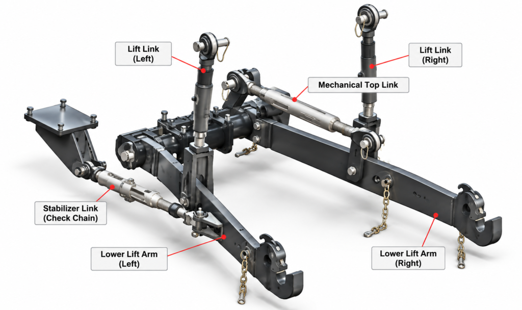
The most important dimensions are:
- Three-point hitch category
- Retracted pin-to-pin length
- Extended pin-to-pin length
- Tractor-side pin diameter
- Implement-side pin diameter
- Mounting width
- Available clearance
The hydraulic top link should provide approximately the same usable adjustment range as the original mechanical link.
A cylinder that is too long when fully retracted may prevent some implements from reaching the required angle, while a cylinder with insufficient extension may limit adjustment in the opposite direction.
Check the Tractor’s Rear Hydraulic System
Most hydraulic top links use a double-acting hydraulic cylinder, which requires hydraulic flow in both directions. If the tractor already has a double-acting rear SCV or rear remote hydraulic outlet, installation is relatively simple. If no rear hydraulic remote is available, an additional hydraulic circuit may be required.
In the Kubota L2501 case, the author considered three possible approaches: installing an OEM rear hydraulic kit, connecting a new valve into the tractor’s existing hydraulic system, or using a kit connected to the front-loader hydraulic circuit. He eventually selected the loader-circuit option because it provided a simpler way to add hydraulic control at the rear. Anders Family Home Page
The exact solution will depend on the tractor model and existing hydraulic system.
Step 1: Remove the Mechanical Top Link
Park the tractor on level ground and lower the attached implement so that there is no load on the three-point hitch.
Remove the retaining clips or pins at both ends of the mechanical top link, then remove the link from the tractor.
Before installing the hydraulic cylinder, compare the mounting ends and overall length with the original top link.
Do not force a cylinder into place if the mounting width or pin diameter does not match.
Step 2: Install the Hydraulic Top Link Cylinder
Position the hydraulic top link between the tractor’s upper hitch point and the implement.
Insert the mounting pins and secure them with the appropriate locking clips.
Make sure that the hydraulic ports, hoses and any integrated valve block have enough clearance throughout the full movement of the three-point hitch.
The cylinder should be installed so that hoses do not rub against the tractor, PTO shaft, implement frame or other moving components.
Step 3: Connect the Hydraulic Hoses
Connect the two hydraulic hoses from the top link cylinder to the tractor’s double-acting rear hydraulic circuit.
Check that:
- The hose fittings match the cylinder ports
- The quick couplers match the tractor outlets
- Hose length is sufficient
- Hoses are not excessively long
- Hoses are protected from sharp edges and moving parts
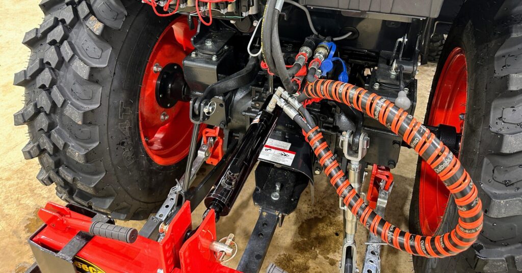
This is one of the areas where installation may require adjustment. Before final tightening, check that the rear hydraulic connection bracket, hoses and fittings do not interfere with the tractor toolbox, body panels, PTO area or three-point hitch movement. The exact hose length and fitting type will vary by tractor.
Step 4: Route and Secure the Hoses
Correct hose routing is important for both safety and service life.
Leave enough slack for the three-point hitch to move through its full range, but avoid large loops that could catch on the implement or tires.
Where necessary, use hose sleeves, clamps or protective guards.
This is one of the areas where real installations can require adjustment. In the Joe Anders installation, the rear hydraulic connection bracket initially interfered with the tractor toolbox, so the mounting position had to be changed.
This is why clearance should always be checked before final tightening.
Step 5: Test Extension and Retraction
Start the tractor at low engine speed and operate the rear hydraulic control slowly.
Extend and retract the hydraulic top link several times.
Check for:
- Smooth cylinder movement
- Correct direction of operation
- Hydraulic leaks
- Hose movement
- Interference with the tractor or implement
- Adequate adjustment range
If the cylinder moves in the opposite direction from what the operator expects, the two hydraulic hoses can normally be exchanged at the rear remote.
Step 6: Check the Full Three-Point Hitch Movement
Raise and lower the three-point hitch through its full working range.
At the same time, test the hydraulic top link in both retracted and extended positions.
Pay particular attention to clearance around:
- PTO shaft
- Hydraulic hoses
- Implement frame
- Tractor body
- Rear tires
- Top-link mounting bracket
The cylinder should never become the mechanical stop for the hitch system.
Hydraulic Top Link With a Locking Valve
Some hydraulic top links include a pilot-operated check valve or locking valve.
This type of valve helps hold the cylinder in position after adjustment, reducing unwanted movement caused by internal leakage in the tractor hydraulic control system.
A locking valve can be useful for applications such as grading, tillage, mowing and land leveling where maintaining a consistent implement angle is important.
Common Installation Problems
Most hydraulic top-link installation problems are related to fitment or hydraulic connections rather than the cylinder itself.
Top link is too long when retracted:
The cylinder may not allow the implement to tilt far enough forward.
Top link does not extend far enough:
The cylinder stroke or extended length may be insufficient for the application.
Hoses are too short:
The three-point hitch may pull on the hoses when raised or lowered.
Hoses interfere with the PTO or implement:
Reroute and secure the hoses before operating the tractor.
Cylinder will not move:
Check the quick couplers, rear hydraulic valve, hose connections and tractor hydraulic pressure.
Cylinder slowly changes position under load:
Check the tractor control valve and consider using a hydraulic top link with an integrated locking valve.
What to Measure Before Ordering a Hydraulic Top Link
To avoid installation problems, provide the following information when selecting a replacement or custom hydraulic top link:
| Measurement | What to Check |
|---|---|
| Hitch Category | Cat. 1, Cat. 2 or Cat. 3 |
| Retracted Length | Pin center to pin center |
| Extended Length | Pin center to pin center |
| Pin Diameter | Both mounting ends |
| Mounting Width | Tractor and implement ends |
| Hydraulic Connection | Port thread and quick coupler |
| Operating Pressure | Tractor hydraulic system |
| Application | Box blade, mower, plow, etc. |
Photos of the original mechanical top link and tractor mounting points can also help confirm compatibility.
Custom Hydraulic Top Links for Tractor Applications
AISOAR manufactures hydraulic top link cylinders for agricultural tractors and three-point hitch applications.
Available configurations include Category 1, Category 2 and Category 3 hydraulic top links, ball-joint ends, hook-type ends, customized stroke, customized retracted and extended length, and integrated locking valves.
For replacement applications, a hydraulic top link can be manufactured according to tractor model, dimensional measurements, drawings, samples or OEM reference information.
Frequently Asked Questions
Can I install a hydraulic top link myself?
If the tractor already has a suitable double-acting rear hydraulic remote and the correct cylinder has been selected, installation is generally straightforward. If an additional hydraulic valve or rear remote circuit needs to be installed, the work becomes more complex and should follow the tractor manufacturer’s hydraulic specifications.
Do I need rear hydraulic remotes for a hydraulic top link?
Normally yes. A double-acting hydraulic top link requires hydraulic flow in both directions. If no rear remote is available, an additional hydraulic valve or hydraulic kit may be required.
How long should hydraulic top link hoses be?
The hoses should be long enough to allow full three-point hitch movement without being stretched, but short enough to avoid excessive loops or interference. There is no universal hose length because tractor layouts vary.
Should a hydraulic top link have a check valve?
Not always, but an integrated pilot-operated check valve can help maintain cylinder position when stable implement angle is important.
Conclusion
Installing a hydraulic top link can significantly improve the convenience of operating rear-mounted implements. The most important steps are selecting the correct cylinder size, confirming the tractor’s hydraulic connection, routing the hoses safely and checking full hitch movement after installation.
A well-matched hydraulic top link should provide sufficient adjustment range without interfering with the tractor, PTO or attached implement. For a custom hydraulic top link, provide AISOAR with the tractor model, hitch category, retracted and extended length, pin dimensions and hydraulic connection so the correct cylinder configuration can be selected.


