 ES
ES RU
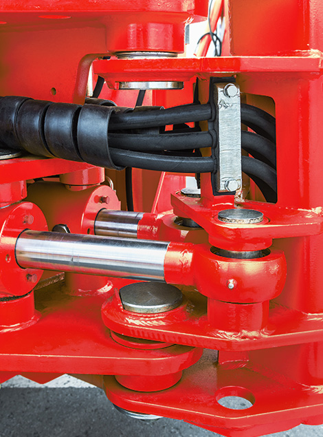
RUCartridge counterbalance valves
Counterbalance valves are used to prevent oil from leaving a cylinder that is holding a load. Without the counterbalance valve, the load would move in an uncontrollable manner if oil pressure is lost for some reason. In a sense, they act as adjustable pressure relief valves and are often used where line pressures can spike. Essentially, in the counterbalance valve, a relief valve sets up a back-pressure in the hydraulic circuit.
Counterbalance valves have adjustable springs and should be set at least 30% over the maximum induced load pressure to allow the valve to reseat properly, i.e. 1.3 times the load-induced pressure. Setting up a counterbalance valve should be performed by trained hydraulic personnel.
A counterbalance valve acts according to three distinct stages of operation, as shown below.
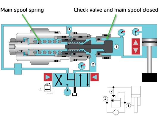
Stage 1 – The directional valve is centered: ports 2 and 3 are directed to tank. The counterbalance valve spool and check valve are closed which prevents oil flow out of the cylinder rod, thus preventing the load from lowering. This is why counterbalance valves are used – to prevent the load from moving when there is no pressure in the supply lines, such as when the solenoid valve is centered or there is a broken hose. This is also why counterbalance valves are normally mounted directly to the hydraulic cylinder on a small valve block.
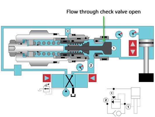
Stage 2 – Lifting load: port 2 is pressurized and port 3 is depressurized. Flow check valve 1 opens, allowing oil into rod end of cylinder, thus raising the load. When the load is lifted all the way, the check valve closes due to its light spring return.
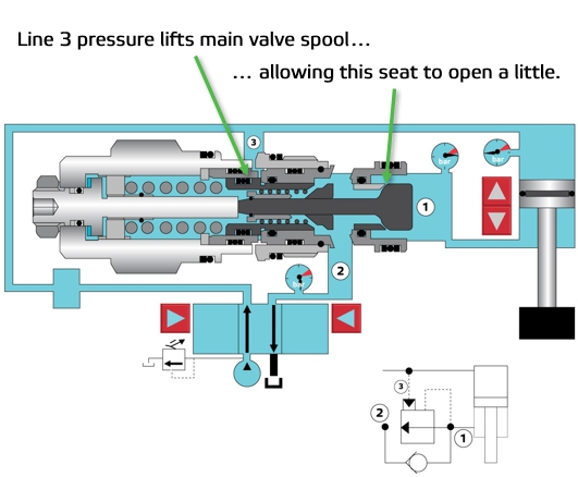
Stage 3 – Lowering load: port 3 is pressurized. This lifts the main spool which allows flow from the cylinder rod end through counterbalance valve to tank port 2. If the load moves down too rapidly, oil pressure in line 3 will decrease, which closes the main valve spool, thus slowing or stopping the load movement. This is another purpose of a counterbalance valve – to move overhung loads smoothly through the stroke of the cylinder (no runaway loads).
For more information on maintaining your hydraulic system, contact your Aisoar representative.
Hangzhou Aisoar hydraulic technology Co.,Ltd
Tel: 86-571-87920309
Fax: 86-571-87926329
Mob&Wechat&Whatsapp: +86 13588456446
Email:Jack@ai-soar.com